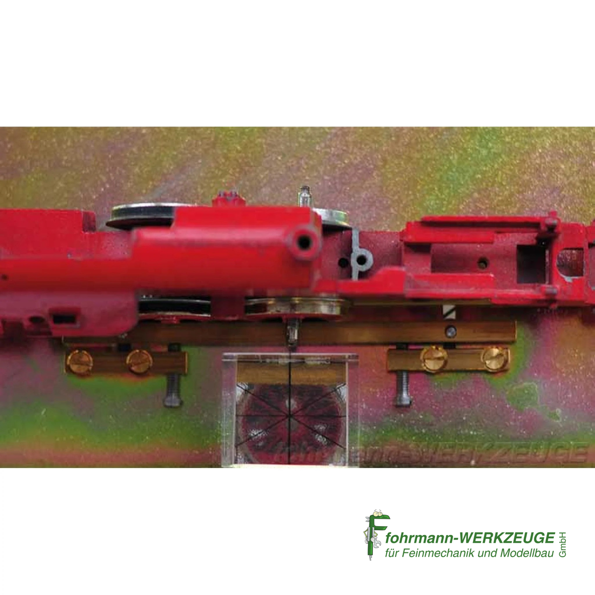
90-degree offset device for crank wheels of steam locomotives
90-degree offset device for crank wheels of steam locomotives
Couldn't load pickup availability

SKU:90838
Precision for Your Steam Locomotives: 90 Degree Offset Jig for Crankshafts
With the 90 Degree Offset Jig for Crankshafts of Steam Locomotives from fohrmann.com, you can achieve an exact setting of the 90° offset on H0 steam locomotives. This special tool is essential for precisely aligning the crankshafts of your models, thus ensuring the authentic running of your locomotives. The delivery includes illustrated instructions and a novel prism with a crosshair for exact determination of the offset.
Optional: Extension for Gauge TT, H0m, N, and H0e
A special feature of this jig is its optional expandability. With a separate add-on part, you can also use the tool for gauges TT, H0m, N, and H0e. Thus, the 90 Degree Offset Jig is a versatile tool for a wide range of model railway layouts.
Video Tutorial: 90 Degree Offset Jig in Action
Detailed Instructions for Setting the Crank Drive of Steam Locomotive Axles
The 90 Degree Offset Jig is used for the precise setting and correction of the 90° crank offset in steam locomotives. The tool consists of a base plate with a fixing device and a prism with a crosshair.
Application for Permanently Installed Axles and Individual Axles:
You can precisely adjust entire chassis, as found for example in Fleischmann models with axles permanently installed in the chassis. The adjustment of individual axles is also possible without any problems. The jig allows for the exact setting of both the vertical line (axle point - crankpin) and the horizontal line (axle center - crankpin).
Step-by-Step Instructions for Perfect Adjustment:
- First, attach an axle to the base plate.
- After a preliminary adjustment, check the offset with the prism. Align the crosshair forward towards the clamped axle.
- View the prism from above and fix the vertical line so that the crankpin and the axle point form a continuous line.
- Secure the wheel disc with the two screws on the fixing part to prevent slipping.
- After the prism is set, turn the plate over.
- Now set the horizontal line: The center point of the axle must form a horizontal line with the crankpin. Check this again with the prism.
Troubleshooting and Repetition for Optimal Results:
If the adjustment is faulty, proceed as follows: For very tight wheel discs, remove the axle and correct it visually. Then restore the basic setting and check the vertical line again. Turn the plate over and check the horizontal line. This process may need to be repeated two or three times to achieve a perfect result.
Tools for Model Railways, Wheels & Axles, and Model Building Tools can also be found with us.
Downloads
Manufacturer's specifications
Manufacturer's specifications